Technical Drawing
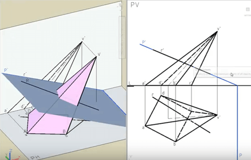
Diedric system: Intersections of planes with solids
Images
3d model information
Technology:
FDM
Material:
PLA
Sizes:
100x50x100 (aprox.)
Accuracy:
Medium
Resistance:
Low
Printing time:
4h
Number of pieces:
2 X 8 = 16 pieces
STL Files Viewer
Summary
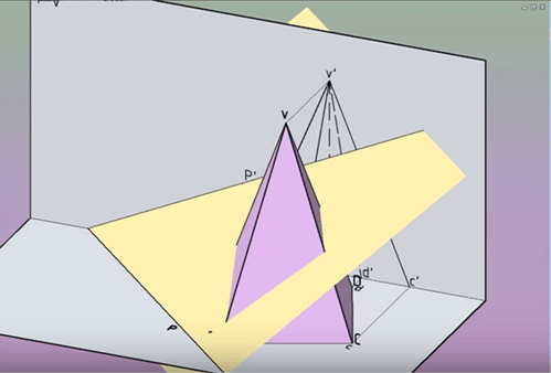
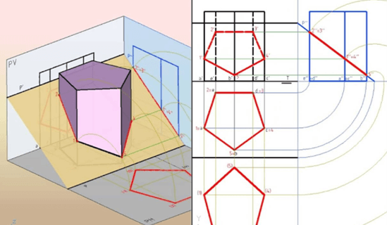
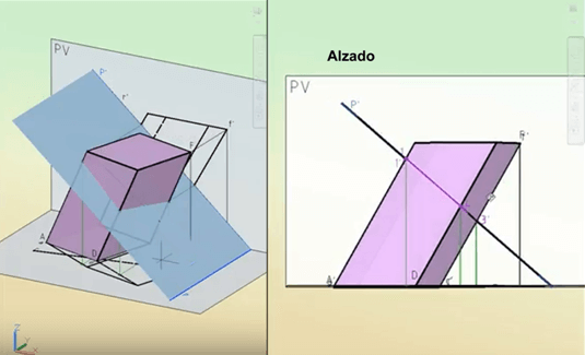
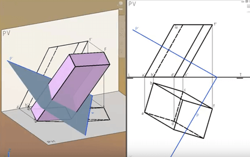
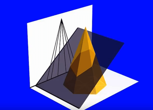
This activity is about drawing in diedric system intersections of solids (cylinders, prisms, cones, cubes, pyramids, tetrahedrons…) with planes in different angles. Students will have to draw the diedric projections of a solid intersected by a plane with a certain angle α. After the teacher explanation of the activity, students will use the 3D printed solids cut in two pieces, according to the intersection of the plane with a certain angle. Then, they will be able to see the resultant shape of the section in the solid.
Learning objectives
- To distinguish among different types of projections.
- To understand the fundaments of diedric system, describing the procedures to obtain projections and their related normalization standards.
- To learn the geometrical basis that determines parallelism and perpendicularity in diedric system.
- To draw according to diedric system rules elements like: point, straight line and plane.
- To develop three-dimensional vision among students, who must be able to imagine the result of the intersections with the solids.
Teacher preparation
- The Technical Drawing teacher will prepare the worksheet and digital presentation to introduce the activity to the students.
- Both materials and drawing tools will be ready to use in the technical drawing classroom.
- The teacher explains the topic and objectives of the activity.
- Students must know previously the basics of diedric system.
- Explanation of 3D printers functioning and 3D design guide.
Teacher explanation
- Students will place the 3D model of the solid (cylinder, prism, cone, cube, pyramid or tetrahedron) in the horizontal plane of a trihedron.
- Then, they must imagine that an oblique plane intersects with it in a certain angle α.
- Once they have visualized this intersection and the resultant cutting shape in the angle, they will manipulate and investigate the 3D printed solids cut by the planes.
- Finally, they will have to draw the horizontal and vertical projections of the solid and the section produced by the intersection.
Student activity/Steps
- Students will place the 3D model of the solid (cylinder, prism, cone, cube, pyramid or tetrahedron) in the horizontal plane of a trihedron.
- Then, they must imagine that an oblique plane intersects with it in a certain angle α.
- Once they have visualized this intersection and the resultant cutting shape in the angle, they will manipulate and investigate the 3D printed solids cut by the planes.
- Finally, they will have to draw the horizontal and vertical projections of the solid and the section produced by the intersection.
General Info
Age of students
15-16
Skills needed
3D printing, computer design
Duration
3 periods
Individual/Groups
Individual
Materials
PLA, paper
Tools
ruler, pencil, rubber
Software
Cura, Tinkercad
License Info
License name:
Attribution 4.0 International (CC BY 4.0)
License details:
You are free to:
Share — copy and redistribute the material in any medium or format
Adapt — remix, transform, and build upon the material
for any purpose, even commercially.
Under the following terms:
Attribution — You must give appropriate credit, provide a link to the license, and indicate if changes were made. You may do so in any reasonable manner, but not in any way that suggests the licensor endorses you or your use.
No additional restrictions — You may not apply legal terms or technological measures that legally restrict others from doing anything the license permits.
More info:
I printed it
If you printed this exercise you can register and share it with the community:
Create a new accountOr Login if you are registered.
